Industrial Equipment Model - Large Material Assembly#
Overview#
CM MES supports production models ranging from high-volume discrete manufacturing to low-volume, long-cycle assembly of large equipment. This guide provides a modeling recommendation for the final assembly of large-sized Materials, such as HVAC units, Switch Gears, Motors, Heavy Machinery, and Aerospace structures, within the Industrial Equipment Template.
Large Materials typically move through a small number of physical stations representing major assembly stages, staying at each stage for an extended period, while multiple Employees work on different parts of the same unit. This differs from the classic MES flow model, where a Material moves sequentially through each distinct operation Step. A Step-per-operation Flow does not scale well when several Employees work concurrently on the same physical unit, or when work at a single Step spans hours or days rather than minutes.
For manual operations, an alternative approach can be modeled based on Process Activities to represent both the sequential and parallel portions of a large assembly process, without requiring a separate Step for every operation.
Business Context#
Final assembly of large equipment shares a common set of characteristics across industries, regardless of the specific product:
- The unit being assembled is large or heavy enough that it progresses through only a small number of physical stages, sometimes staying in a single location for the entire assembly (typical of Aerospace and Heavy Machinery), and sometimes moving through a handful of Steps (typical of HVAC, Switch Gear, and Motor assembly).
- Multiple trades (mechanical, electrical, piping, controls, quality) work on the same unit, sometimes simultaneously.
- Assembly duration is measured in hours or days, not minutes.
- The Bill of Material is complex, often multi-level, combining purchased components, in-house sub-assemblies, and configuration-driven variants.
- Engineer-to-Order and configure-to-order variability is common, with Product Characteristics driving which components and operations apply.
- Traceability and quality requirements are high, often down to the sub-assembly or component level.
These characteristics apply consistently across HVAC units, Switch Gears, Motors, Heavy Machinery, and Aerospace structures, even though the specific components, trades, and number of physical stages vary by industry and by product size.
MES Modeling#
Key CM MES Concepts Used in This Recommendation Guide#
This guide builds on a small set of CM MES concepts. Each is only summarized here; see the linked documentation for the full details.
- Flow ↗: the overall production route a Material follows, made up of Steps.
- Step ↗: a stage in the Flow where a Material is located and where work is tracked.
- Process Activity: an operation performed on a Material, with its own Checklist ↗ (which can include Data Collection parameters and BOM Items). Process Activities are defined per Flow through a Process Activity Definition (PAD), and several can be open and worked on concurrently for the same Material.
- Execution window (Earliest / Latest Step): each PAD is scoped through its range to either a single Step or multiple Steps. A Process Activity is only created for a Material once it reaches the PAD's Earliest Step, and must be completed by its Latest Step, if one is defined.

Modeling Recommendation#
Product Structure (BOM)#
For large assembled Materials, composed of small sub-assemblies that will be brought together in a larger final assembly, each sub-assembly should have its own process Flow, BOM, and Production Order if integrated with ERP. For the Final Assembly, the final product Production Order and BOM would consume the produced sub-assembly Materials. This mirrors the pattern already used in the Industrial Equipment Template master data, where a Finished Good (e.g., a Rooftop Unit) consumes Semi-Finished Goods produced in their own Fabrication Flows (see Products and Flows Structure in the Industrial Equipment Master Data Guide).
A component should be modeled as its own Material with its own Flow (a sub-assembly) when:
- It requires its own production or assembly operations before it is ready to be consumed.
- It needs individual traceability or genealogy (serial number, lot, certificate).
- It is produced ahead of time and stocked for consumption by the final assembly (Kanban-style replenishment).
- It is complex enough to justify its own set of Process Activities, Checklists, or Data Collections.
A component can stay as a simple BOM line (purchased part or kit) when:
- It is used as received, with no production or assembly step of its own.
- It does not require individual traceability beyond what is captured at the parent Material level.
- It is a low-complexity item (fasteners, gaskets, small hardware) more practically managed as inventory than as a tracked sub-assembly.
This decision should be applied per major functional sub-system of the equipment (for example: structural frame, electrical control panel, motor unit), not per individual part, to keep the model manageable.
See also: BOM ↗ in the CM MES Documentation Portal for the base entity documentation.
Flow/Routing Structure#
Model the manual operations for final assembly as a small number of Steps representing physical assembly stations or stages, not one Step per operation. A large Material typically stays at the same Step, or moves through very few Steps, for the entire assembly process.
Within each Step, break down the actual work into Process Activities. This keeps the Flow itself simple and stable, while the work breakdown, and its sequencing or parallelism, is expressed at the Process Activity level (see Process Activities).
Process Activities#
Process Activities are the mechanism this guide recommends for representing the parallel portions of the assembly process without adding Steps. Sequencing between stages is still carried by the Step sequence itself, not by a dependency between Process Activities: there is no native mechanism for one Process Activity to block another at the same Step.
- Parallel portions: define independent, non-exclusive Process Activities scoped to the same Step or Step range, so several Employees can check in and work concurrently on the same Material. Use AllowMultipleEmployees if more than one Employee needs to check into the same Process Activity.
- Sequential portions: enforce ordering through the Step sequence (see Flow/Routing Structure), not through the Process Activities themselves. Scope each sequential stage's Process Activities to its own Step (or Step range), so a later stage's Process Activities are only created once the Material has advanced to the corresponding Step.
- Mixed portions: combine both patterns, using a handful of Steps to carry the sequential stages, each with several concurrent, non-exclusive Process Activities covering the parallel work within that stage. A Process Activity can also be scoped to span more than one Step, when a single work package genuinely runs across several stages without needing to pause.
- Conditional Process Activities: use the PAD's Condition Expression to create a Process Activity only when it is relevant for a given Material, based on its properties, attributes, or Product Characteristics. This is particularly useful for the Configure-To-Order (CTO) variability described in Business Context: instead of exposing every possible Process Activity to the operator and relying on the operator to Skip activities that are not applicable, the Process Activities can be configured with pre-defined condition rules based on Product Characteristics. These will then be transparent for operations, that will only see the activities applicable to that unit's configuration, reducing unnecessary interaction with the MES.
When using Process Activities, any related manual assembly BOM or Data Collection, should be associated directly to the Process Activity's Checklists, instead of using the Step's BOM/Data Collection/Checklist context.
Note
Process Activities are best suited to manual operations that can be performed concurrently, without a need for Resource tracking. If Resource tracking is required, it must be modeled at the Step level (Track-In/Track-Out), independently of Process Activity execution; Steps where Resource tracking is not required can be modeled as Pass Through, with progress tracked at the Process Activity level instead.
Modeling Guidance#
This section covers practical modeling choices to keep in mind when applying the modeling recommendation, without going into system configuration steps.
- Name Process Activities by work package, not by system label. Employees see the Display Name directly in the Process Activities View, so it should match how the trade or task is referred to on the shop floor (for example, "Electrical Wiring", not "PA-04").
- Match granularity to how work is actually assigned and reported. Group tasks into a Process Activity at the level a single Employee or trade would report progress on. Modeling every micro-task as its own Process Activity adds administrative overhead without adding real traceability value; modeling too coarsely loses the ability to track parallel work independently.
- Keep one Checklist per Process Activity Definition, scoped to that work package. The Checklist, Data Collection, and BOM Items of a PAD are fixed for that Process Activity, so avoid reusing the same Checklist across unrelated Process Activities just to save setup effort.
- Use Priority to help Employees choose what to work on next, when several Process Activities are open at the same time for the same Material.
- Keep check-in behavior (Auto Begin, Enable Check-In, Auto Check-In On Begin, Auto Check-Out On Close) consistent across Process Activities in the same Flow, so Employees have a predictable experience regardless of which Process Activity they open. These defaults can be set once at the Entity Type Properties level, rather than repeated per Process Activity Definition.
- Finalize the Process Activity set before making the Flow version Effective. Process Activity Definitions can only be added, changed, or removed while the Flow version is in Created state. Once Effective, changes require a new Flow version, and Process Activities already In Progress on the current version block Definition changes until they are completed or canceled.
These choices affect how usable and maintainable the model is in practice, but do not change the underlying modeling recommendation.
Considerations & Trade-offs#
The modeling recommendation is a starting point, not a fixed formula. The right level of granularity depends on the customer's operational maturity and on what actually needs to be tracked.
- Granularity vs. setup and usability overhead. Every Process Activity Definition needs its own Checklist, and shows up as its own entry in the Process Activities View. Modeling every sub-task as a separate Process Activity increases traceability, but also increases configuration effort and the number of items Employees need to manage on the shop floor. Start with Process Activities scoped to whole work packages, one per trade or major task, and only split further where independent tracking or genuinely concurrent execution is required.
- Hard sequencing requires Steps, not just Process Activities. Because there is no dependency mechanism between Process Activities (see Process Activities), the only way to guarantee that one piece of work is fully finished before another starts is to place them in different Steps. If a customer needs strict, system-enforced ordering between two work packages, expect a Step split, not just an additional Process Activity.
- Process Activities do not replace Resource tracking. If Resource-level metrics (utilization, capacity, OEE) are required for a given operation, that operation should remain a Step with Track-In/Track-Out, not a Process Activity. Reserve Process Activities for manual work where Resource-level tracking is not a requirement.
- Flow-level configuration vs. product variability. A Process Activity Definition's Checklist, Data Collection, and BOM Items are fixed for the Flow it belongs to; the Condition Expression can decide whether a Process Activity is created for a given Material, but cannot change what it contains. Products with highly variable assembly content may need either several Flows or a more generic, shared Checklist design, and both come with a maintenance cost.
- Match the model to the customer's operational maturity. Customers new to MES, or with simpler operations, generally adopt a model faster when it has fewer Steps, fewer Process Activities, and little conditional logic, even if it is less precise. Customers with tighter Engineer-to-Order or traceability requirements can justify the added configuration effort and Employee training that a more granular model requires.
- Plan for Flow versioning discipline. Process Activity Definitions can only be changed while a Flow version is Created; once Effective, changes require a new version. Treat the initial Process Activity set as something to stabilize before go-live, and plan future changes through the Flow versioning process rather than as ad hoc edits.
Illustrative Example#
The Industrial Equipment Template's Final Assembly Flow for the Rooftop Unit (InduTech scenario) already applies the mixed pattern described in Process Activities, using three Process Activity Definitions with overlapping Multiple-Step ranges instead of Steps confined to a single unit of work:
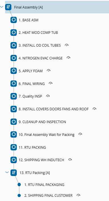
| Process Activity Definition | Earliest Flow Path | Main Flow Path | Latest Flow Path | Role / Certification | Is Exclusive | Allow Multiple Employees |
|---|---|---|---|---|---|---|
| PAD 3 – Assembly IE HVAC | HEAT MOD COMP TUB (2) | INSTALL OD COIL TUBES (3) | APPLY FOAM (5) | Role: InduTech Operator | No | Yes |
| PAD 4 – Assembly IE HVAC | NITROGEN EVAC CHARGE (4) | APPLY FOAM (5) | FINAL WIRING (6) | Certification: BAY 2 Certification | No | No |
| PAD 5 – Assembly IE HVAC | FINAL WIRING (6) | INSTALL COVERS DOORS FANS AND ROOF (8) | INSTALL COVERS DOORS FANS AND ROOF (8) | Role: InduTech Operator, Certification: BAY 3 Certification | No | Yes |
Each Process Activity Definition's range overlaps with the next: PAD 3 and PAD 4 both cover Steps 4 and 5 (NITROGEN EVAC CHARGE and APPLY FOAM), and PAD 4 and PAD 5 both cover Step 6 (FINAL WIRING). For a Material at one of those boundary Steps, two Process Activities can be open at the same time, each restricted to a different Role or Certification. None of the three is Exclusive, so an Employee checked into one of them can still be checked into another Process Activity if needed. PAD 3 and PAD 5 additionally allow more than one Employee to check into the same Process Activity at once, while PAD 4 is limited to a single Employee at a time.
This is a real instance of the mixed pattern described in Process Activities: the work is not split into hard sequential blocks that fully finish before the next one starts. An Employee qualified for the next stage can begin as soon as the Material reaches the Earliest Flow Path of their Process Activity, while the previous Process Activity can still be finished up to its own Latest Flow Path, several Steps later. This avoids idle time at Step boundaries without requiring the Steps themselves to be merged.
The parallelism described above comes from the overlap between PAD 3, PAD 4, and PAD 5, not from within any single one of them: each Process Activity Definition still represents one continuous task, performed across its own range of Steps.
A further, separate opportunity exists at PAD 5. INSTALL COVERS DOORS FANS AND ROOF bundles four physically distinct components - covers, doors, fans, and roof - that are plausibly independent of each other. If that is confirmed, PAD 5 could be split into four independent, non-exclusive Process Activity Definitions, all scoped to that same Step, so that four different Employees could work on the four components at the same time. This would add parallelism inside a single Step, on top of the overlapping-range parallelism that already exists between PAD 3, PAD 4, and PAD 5.
Notes and Exceptions#
The following are known platform behaviors and restrictions relevant to this modeling pattern. The full list is maintained in the Process Activities User Guide; only the points most relevant to large-material assembly are repeated here.
- No Resource-level tracking. Process Activities are aimed at manual operations performed concurrently, without a need for Resource tracking. If Resource tracking is required for an operation, it must be modeled at the Step level (Track-In/Track-Out), independently of Process Activity execution.
- Checklist, Data Collection, and BOM are fixed per Flow, not per Product/Production Order/Material. A Process Activity Definition's Checklist is tied to the Flow it belongs to. If different Products or Production Orders genuinely need different Checklists, Data Collection, or BOM for the same work package, they need separate Flows; the Condition Expression can only decide whether a Process Activity is created, not change its content.
- Checklist requirements. The Checklist linked to a Process Activity Definition must be of scope Material Tracking, with execution mode Long Running. Instruments should be avoided in a Process Activity's Data Collection.
- Process Activity time is independent of Step Cycle Time. Time tracked at the Process Activity level does not automatically feed Step Cycle Time. Scheduling and performance reporting features that depend on Step Cycle Time need it modeled separately, at a level that already accounts for the estimated average time of the Process Activities expected to run within that Step.