Creating a Flow Model#
Estimated time to read: 19 minutes
Overview#
The following table defines some key concepts that are relevant for this tutorial:
| Concept | Description |
|---|---|
| Step | A Step is the smallest process tracking unit for a Material. |
| Flow | A Flow defines a sequence of Steps that a certain Material must follow. It’s possible to define a default Flow for every Product and Product Group that will be assigned automatically by the system when first creating a Material of that Product. A Flow can contain Flow Items of type Flow or Step. Since a Flow may contain duplicate Flow Items, the specific position within the Flow is called a Flow Path and it has a unique address within the Flow. |
| Product | A Product is a specification of what a current Material is or what it’s intended for the Material to become. A Product being a specification has no physical existence. |
| Material | A Material is a physical instantiation of a Product and it has a quantity associated with it. A Material, in Critical Manufacturing MES, is a very generic object and it can represent raw materials, semi-finished and finished goods, durables and work-in-progress (WIP). In addition to a reference to a Product, it is associated with a Flow, a Step, and a Facility. |
| Service | A Service is a certain process capability that is required by a Material for a certain context, and that are provided by Resources. When a Resource provides the Service that is required by the Material, the Material can be dispatched and processed at that Resource. |
| Reason | A Reason is used to categorize losses and bonuses as well as to justify Reworks, Off-Flows and Holds. |
Table: Core concepts
The next figure describes the simplified Flow object model:
graph TD
    A1[Flow] -.- A2[Child Flow]
    A1 -.- A3[Step]
    A3 --> A4[Reason]

classDef mermaid_title color:#000, fill:#fafafa, stroke:#fafafa, stroke-width:0x, font-size:100%, font-weight:200;
classDef mermaid_start color:#000, fill:#fafafa, stroke:#fafafa, color:#fafafa, stroke-width:0x, font-size:100%, visibility: hidden;
classDef mermaid_businessdata color:#000, fill:#65CDE8, stroke:#65CDE8, stroke-width:0px, font-size:100%;
classDef mermaid_nonbusinessdata color:#000, fill:#B7DEE8, stroke:#B7DEE8, stroke-width:0px, font-size:100%;
classDef mermaid_entity color:#000, fill:#FB9F53, stroke:#FB9F53, stroke-width:0px, font-size:100%;
classDef mermaid_entitylinked color:#000, fill:#FCD5B5, stroke:#FCD5B5, stroke-width:0px, font-size:100%;
classDef mermaid_context color:#000, fill:#B9CDE5, stroke:#B9CDE5, stroke-width:0px, font-size:100%;
classDef mermaid_optional color:#000, fill:#B7DEE8, stroke:#65CDE8, stroke-width:1px, font-size:100%, stroke-dasharray: 5 5;
class Main mermaid_entity
class A1 mermaid_businessdata
class A2,A3 mermaid_entitylinked
class A4 mermaid_context
Flow Item#
As previously mentioned, a Flow consists of a combination of Flow Items, which can be of type Step or Flow. So, a Flow may contain exclusively Steps, Flows, or a mixture of both Flows and Steps.
graph TD;
A[TopMost Flow]
A --> B(Step 1)--> C(Step 2)--> D(Step 3)--> E(Step 4)
A --> F(Flow 1)--> G(Flow 2)--> H(Flow 3)--> I(Flow 4)
A --> J(Flow 1)--> K(Step 1)--> L(Step 2)--> M(Flow 2)
classDef mermaid_title color:#000, fill:#fafafa, stroke:#fafafa, stroke-width:0x, font-size:100%, font-weight:200;
classDef mermaid_start color:#000, fill:#fafafa, stroke:#fafafa, color:#fafafa, stroke-width:0x, font-size:100%, visibility: hidden;
classDef mermaid_businessdata color:#000, fill:#65CDE8, stroke:#65CDE8, stroke-width:0px, font-size:100%;
classDef mermaid_nonbusinessdata color:#000, fill:#B7DEE8, stroke:#B7DEE8, stroke-width:0px, font-size:100%;
classDef mermaid_entity color:#000, fill:#FB9F53, stroke:#FB9F53, stroke-width:0px, font-size:100%;
classDef mermaid_entitylinked color:#000, fill:#FCD5B5, stroke:#FCD5B5, stroke-width:0px, font-size:100%;
classDef mermaid_context color:#000, fill:#B9CDE5, stroke:#B9CDE5, stroke-width:0px, font-size:100%;
classDef mermaid_optional color:#000, fill:#B7DEE8, stroke:#65CDE8, stroke-width:1px, font-size:100%, stroke-dasharray: 5 5;
classDef mermaid_state color:#000, fill:#d7e4bd, stroke:#000, stroke-width:1px, font-size:100%, font-weight:300;
class A mermaid_businessdata
class F,G,H,I,J,M mermaid_entity
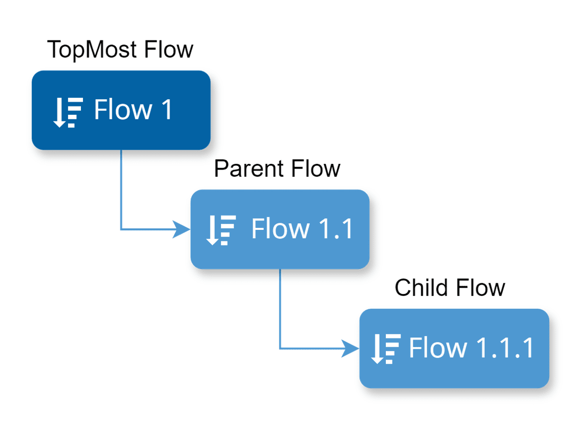
class B,C,D,E,K,L mermaid_entitylinkedSince Flows can contain other Flows, it is important to understand the correct referencing approach. In the provided scenario, where a Flow has two Child Flows, Flow 1 would be the TopMost Flow, Flow 1.1 would be the Parent Flow, and Flow 1.1.1 would be the Child Flow. However, when delineating the relation between Flow 1 and Flow 1.1, we could also define Flow 1.1 as a Child Flow of the TopMost Flow.
Another possible scenario is displayed below, where Flow 1 is composed of two Flow Items of different types (Flow 1.1 and Step 3), while Flow 1.1 is comprised of two Flow Items of type Step (Step 1 and 2).
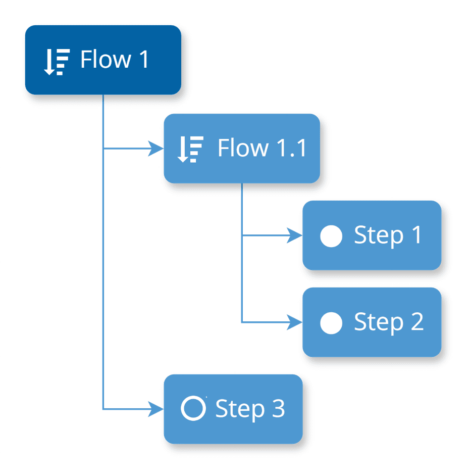
Note
When a Step has Flows at the same level, instead of the usual filled circle icon, it appears as an outlined circle resembling the standard Step icon.
Step Characteristics#
Each Step defines several relevant characteristics that determine the Material tracking and other behavior as listed in the next table:
| Characteristic | Description |
|---|---|
| Sub-Material Track State Depth | Defines the Material level for which Track-in and Track-out will be enabled for the Step. |
| Default Logistic Future Action Execution Mode | Defines whether logistic Future Actions (Split and Merge) will be executed manually or automatically by default for the Step. |
| Processing Type | There are three possible processing types: • Process – in this case, the system maintains the Last Process Step Resource property with the Resource where the Material was last tracked-in • Metrology • Logistical |
| Material Sort Rule Set | Specifies the Sort Rule Set used to sort Material to be displayed in the Step View page. |
| Resource Sort Rule Set | Defines the Sort Rule Set used to sort Resource for Material on this Step. This is used for pushing Material to Resources, answering the question: What is the next Resource for the Material? |
| Split Checklist Mode | Defines what should happen to the Material Checklist Instance when a Material is split in-process: • Create Note – no Checklist Instance is created • Create Copy – creates a copy of the Checklist Instance preserving the current state • Create New – creates and initializes a new Checklist Instance |
| Shipping Allowed | Specifies whether Shipping of Material to another Facility is allowed from this Step or not. |
| Decimal Quantity Allowed | Specifies whether decimal quantities are allowed on Material operations in this Step. When set to false, only discrete quantities are possible. |
| Marks Product Completion | Defines when using Order Management, that the Material must be considered completed when it reaches this Step. |
| Auto Split by Product | Specifies that when using Binning/Grading at the Step, that the Material will be automatically split-by-product after Track-Out of this Step. |
| Material Transfers Allowed | Defines whether Material Transfers can be requested or fulfilled from this Step. |
| Enable Step Certification Requirements | Defines whether the Certification Requirements Context for the Step needs to be checked in addition to the Resource Personnel Requirements for employees performing Material operations on this Step. |
| Enable Time Constraints | Defines whether Time Constraints are allowed to or from this Step. Only if Time Constraints are enabled it will be possible to edit the Time Constraints Context. |
| Set Units | Defines whether the Step defines (enforces) the Material Primary and Secondary Units. If a Step is defined with Set Units, the Primary Units need to be defined. |
| In-Step Sampling | Specifies whether In-Step Sampling (requires Sub-Materials) is enabled for the Step or not. When enabled, the Sampling Pattern Context must be edited. |
| Track-Out Losses Mode | What type of loss screen must be displayed when Tracking-Out material in this Step: • None – no screen is displayed • Main Material – screen is displayed for the main material • Sub Materials – screen is displayed for the sub materials |
| Pass-Through | Defines whether the Material is Pass-Through or not. In a Pass-Through Step, a Material only has to perform a Move-Next. If the Step is not Pass-Through, a Material needs need to be Dispatched, Tracked-In, Tracked-Out and Moved-Next. |
| Storage Services | These properties define the required storage services for storing Material in both Queued and Processed state in this Step. |
| Include in Planning | Defines whether the Step must be included in Schedule Scenarios of type Planning or not. |
| Include in Scheduling | Defines whether the Step must be included in Scheduling or not. |
| Loss Reasons | Defines the Loss Reasons applicable for the Step. Each Loss Reason can be checked to specify whether they apply to: • Record Loss • Terminate • Assemble A Loss Reason at the Step can also specify what was the actual Step where the loss was incurred. |
| Loss Classifications | Defines up to four loss classifications that further classify losses reported on this Step. |
| Hold Reasons | Defines the Hold Reasons applicable for the Step. A material on hold cannot be moved from its current Step or current State. |
| Off-Flow Reasons | Defines the Off-Flow reasons applicable for the Step. Each Off-Flow reason can be configured to specify whether it applies to: • Rework • Temporary Off-Flow The difference between Rework and Temporary Off-Flow is the following: • Reworks must always be defined in advance and thus, they must be configured as part of the flow. • The rework return point can be any Step in the flow. • Rework can only be performed for Materials in state Queued or Processed, but when a Material returns from a Rework it always goes to the state Queued • Temporary Off-Flows are not defined in advance. A Material can be sent temporarily to any Flow. • The Temporary Off-Flow return point is always the Step from which the Material was sent to Temporary Off-Flow. • Temporary Off-Flows can be performed for Materials in state Queued, Dispatched or Processed, and when a Material returns from a Temporary Off-Flow, it always returns to the same state from which it was sent, and to the same Resource (if any). The difference between Rework and Temporary Off-Flow is illustrated in the picture below. 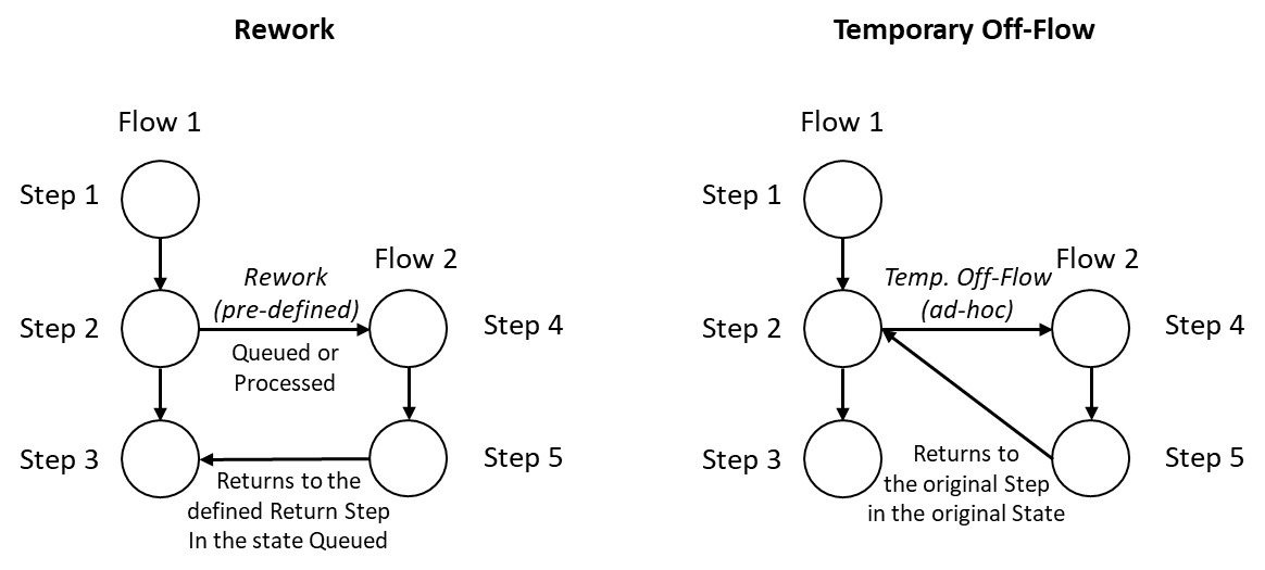  The system supports nesting of reworks and temporary off-flows. The system supports nesting of reworks and temporary off-flows. |
| Bonus Reasons | Defines the Bonus Reasons applicable for the Step. A bonus is the opposite of a loss and it indicates that the material quantity is increased. A common bonus case consists of adding some material which has previously been considered scrap and has been recorded as a loss. |
Table: Step relevant properties
Flow Characteristics#
The table below describes important Flow characteristics.
| Characteristic | Description |
|---|---|
| Versioning | A Flow is versioned object that is subject to change control. |
| Context Resolution | A Material is always at a Flow and at a Step, therefore it’s common for both the Flow and the Step be part of context resolution. Because a Step can be re-used in multiple Child Flows, the Flow that is used in context resolution is not the TopMost Flow of the Material, but rather the immediate Parent Flow of the current Material Step. In the picture below, a simplified version of the Service Context smart table is shown. For Step 1, if a Material would be in Flow 1, the context resolution would resolve the required Service as Service 1; if a Material would be in Flow 2, it would resolve to Service 2; and for all other Flows it would resolve to Service 3.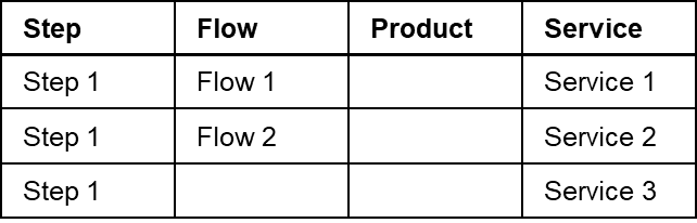 |
Table: Flow characteristics
Types of Flows#
Sequential Flows#
This is the default mode when creating a Flow. A Sequential Flow may include Flow Items of both types (Flows or Steps), may contain optional Flow Items, may be skipped, and can also include Line Steps.
Info
In a Sequential Flow, the final Flow Item cannot be optional.
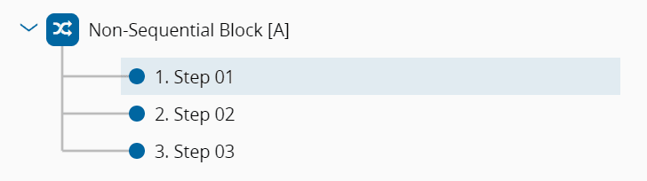
Non-Sequential Blocks#
A Non-Sequential Block defines a set of Steps (typically testing/metrology Steps) that need to be performed on a certain Material but for which the order of execution is not relevant. In the example below, the sequences Step 01 – Step 02 – Step 03; Step 02 – Step 01 – Step 03; and Step 03 – Step 01 – Step 02; are all valid sequences for the Material.
Warning
A Non-Sequential Block Flow must consist solely of Flow Items of type Steps, ensuring there is at least one non-optional Step. If the last Flow Item is a Step, it cannot be an optional one. Moreover, it cannot include Alternate or Line Flows and must not contain repeated Steps, regardless of any variation in their Logical Names.
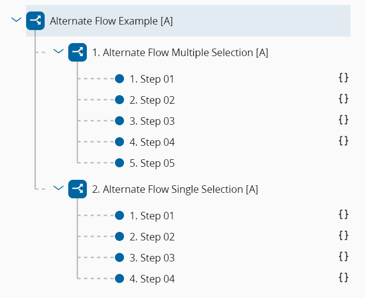
Alternate Flows#
When a Flow is Alternate, only one of its branches, be it made of Flow Items of type Flow or Step, will be taken by a Material. That is, each Flow Item that makes up the Flow is mutually exclusive. The Alternate Flow Selection Type offers two options:
- Single: Only the first Flow Item whose condition resolves to true is considered when attempting to move the Material to the next Step.
- Multiple (default): All Flow Items whose conditions resolve to true are displayed for selection while attempting to move the Material to the next Step.
Warning
An Alternate Flow cannot have optional Flow Items, and it cannot be a Non-Sequential Block or a Line Flow. Additionally, it must not contain duplicated Flow Items, even if their Logical Names differ.
An Alternate Flow with Single Selection requires that every Flow Item has a defined Condition, which can be either an Expression or a Rule.
Line Flows#
The Line Flow outlines the sequential Sub-Steps aligning with the operations conducted across the Sub-Resources of the Line Resource. A Line Flow must only contain Flow Items of type Step, excluding Pass-Through Steps and any Step marked as Is Line. The first and last Step of a Line Flow cannot be optional. Additionally, it must not be a Non-Sequential Block or an Alternate Flow.
Info
For more information, see Line Material Tracking.
Rework Flow Paths#
In a Flow composed of Steps, it’s possible to define one or more Rework Paths at each Step. A Rework Path can be associated with an Off-Flow Reason linked to the Step, indicating its relevance for Rework, and it establishes both the Go To Flow Path and the Return point within the Flow.
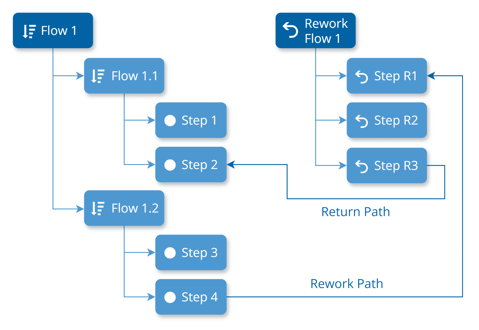
Rework Paths can be defined at the Parent Flow level, allowing Return Paths to any Step within its structure. These Return Paths are anchored to the TopMost Flow where they are defined, rather than to a specific Flow Item. For instance, in the diagram below, the Return Path can be any Step (e.g., Step 1, Step 2, Step 3, or Step 4) within the TopMost Flow (Flow 1).
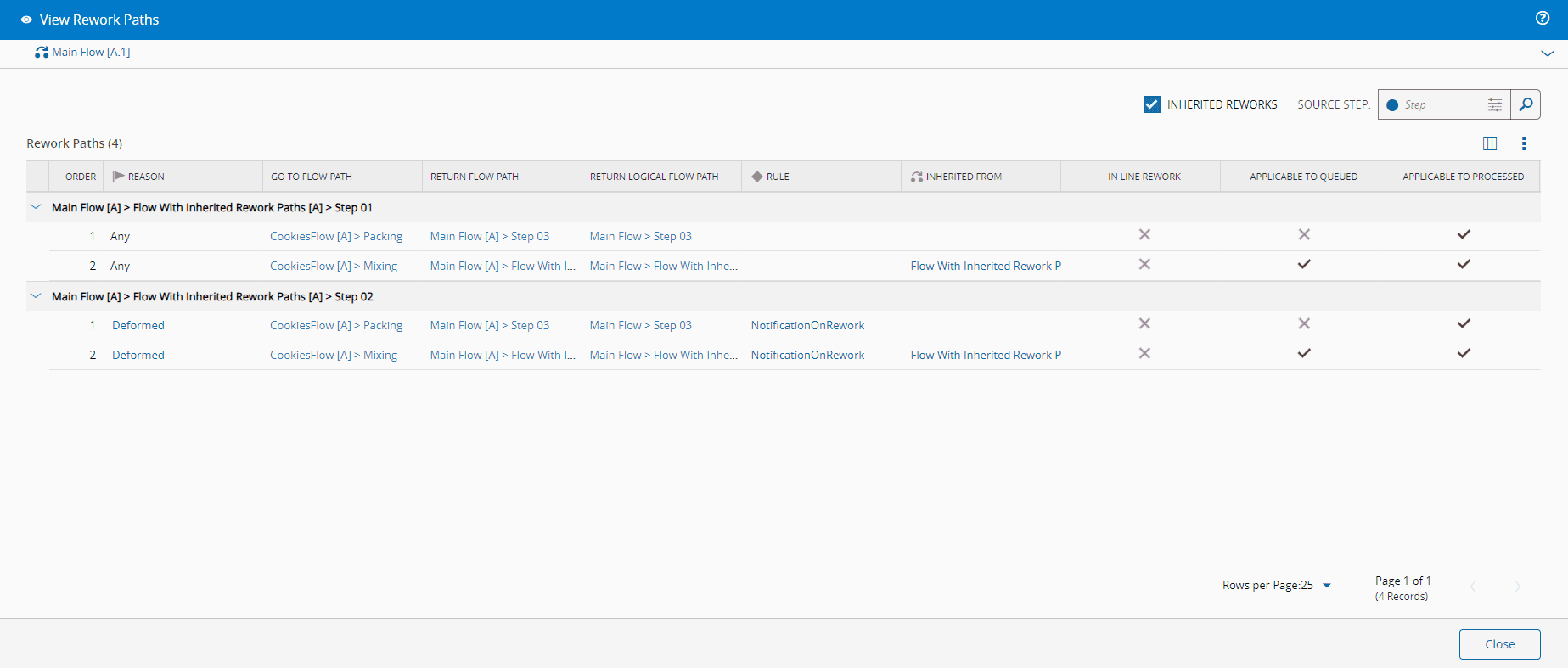
There are no limits to the number and levels of Rework. A Material which is in Rework, can be sent to Rework. Furthermore, a Flow inherits Rework Paths from their inner Flows. If an inner Flow has Rework Paths, they will also be available for Materials processed in the main Flow, alongside any other Rework Paths defined for the main Flow. You can specify whether a Rework Path applies when the Material is in Queued or Processed state. This is controlled by the flags Applies to Queued and Applies to Processed in the Rework Path Entity Type. It's also possible to define a Rule, of scope Material Tracking, triggered when the Material is sent for Rework via a specific Rework Path. This is managed by the On Rework Rule property of the Rework Path Entity Type.
When the Source Rework Flow (i.e., the Parent Flow of the Rework Step) is a Line Flow, the property IsInLineRework cannot be null - it's either set to True or False. If this property is True the Go To Flow must be a Line Flow and all the Steps in this Flow must exist in the current Source Rework Flow.
You can access a comprehensive list of Rework Paths configured for a Flow by selecting the View Rework Paths button located in the action bar.
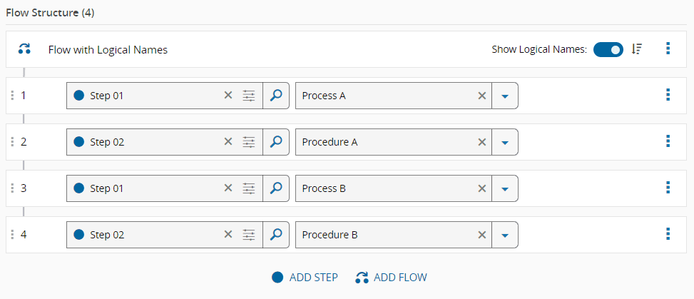
Logical Names#
The reusability potential of Flows and Steps is enhanced through the use of Logical Names and Logical Flow Paths:
-
A Logical Name is an optional qualified name for a Flow or Step within a specific Flow version. This name designates the Intended Usage of the Flow Item.
-
A Logical Flow Path is a simple sequential list of all the Logical Names within the Flow Item.
This approach allows you to avoid duplicating Flow Items and instead reuse them in different contexts or for different purposes. For instance, you can repeat a sequence of Steps with varying parameters (such as Durables, Recipe, BOM, and others) without creating new Flow Items each time.
The Logical Name feature provides the flexibility to specify the usage, purpose, or intent of a Step when creating the Flow. You can use the same Flow Items with different Logical Names across various Flows, except for Alternate Flows, Non-Sequential Blocks, or Line Flows.
Note
Logical Names are predefined and managed at the Flow and Step level. For more information, see How to: Manage Step Logical Names.
Conditional Resolution of Optional Flow Items#
Optional Flow Items, whether of type Step or Flow, are elements that can be skipped during the process. The decision to skip them or not must be made when moving the Material to the next Flow and Step, either manually or automatically through a business rule. Additionally, optional Flow Items or those belonging to Alternate Flows can have associated conditions. These conditions will be evaluated when determining the possible next Steps for a Material, determining the Flow and Step to which the Material can move next taking into account the state and characteristics of the Material at that time. The conditions applied to the Flow Items, determined by the Condition Type property, can be one of the various types listed in the table below.
| Condition Type | Description |
|---|---|
| Expression |
|
| Rule |
|
| Step Sampling |
|
| Sampling Plan |
|
Info
Only Flow Items of type Step belonging to Flows other than Non-Sequential Blocks or Alternate Flows can have the Condition Type set to Step Sampling or Sampling Plan.
Execute Rules on Enter/Exit Step#
You can define Rules to be run when a Material enters or exists a Step. These Rules are linked to DEE Actions, enabling you to execute custom code to be triggered when entering or exiting a specific Step. The management of these Rules is handled by the Flow structure. In the Edit Flow Structure view, you can select a Rule with the scope Material Tracking to be executed for Enter and Exit events of Flow Items of type Step. This functionality is controlled by the On Enter Rule and On Exit Rule properties of the Flow Item.
Visual Conventions#
Critical Manufacturing MES includes icons to help you quickly identify each type of Flow and highlight any special configurations for Flow Items. The table below lists the possible icons and their corresponding meanings.
| Icon | Description |
|---|---|
| Indicates a Sequential Flow | |
| Indicates a Non-Sequential Block | |
| Indicates an Alternate Flow | |
| Indicates a Line Flow | |
| Indicates a Rework Path | |
| Indicates an Optional Flow Item | |
| Indicates a Pass-through Step | |
| Indicates the presence of a Condition | |
| Indicates the presence of a Rule |
Table: Visual Conventions
Step contexts are also represented by icons, making it easier to identify them at a glance. Below is a table listing these icons along with their meanings:
| Icon | Context |
|---|---|
| Service | |
| Resource | |
| Recipe | |
| Parameter | |
| Data Collection | |
| Chart | |
| Checklist | |
| BOM | |
| Durable | |
| Document | |
| Flow | |
| Yield and Cycle Time | |
| Future Action |
Table: Visual Conventions for Step Contexts
In the Context Matrix view, each entity is represented by an icon, and their meanings are provided in the table below:
| Icon | Description |
|---|---|
| Service | |
| Resource | |
| Recipe | |
| Parameter | |
| Data Collection | |
| Chart | |
| Checklist | |
| BOM | |
| Durable | |
| Document | |
| Sampling Pattern | |
| Inspection Plan: | |
| Time Constraints | |
| Flow | |
| Certification Requirements | |
| Yield and Cycle Time |
Table: Visual Conventions for Entities on the Context Matrix View