---
pdfexport: true
alias: tutorials-connectiot-configuration-basic
timetoread: true
tutorial: full
module: Connect IoT (Equipment Integration)
description: "Connect IoT configuration for device integration and automation workflows"
---
# Connect IoT - Basic Configuration Tutorial
Starting with this Basic Configuration, it will provide a structure to build the Connect IoT business logic and the connection to a device. The protocol chosen for this example is OPC-UA. We have used a simple simulator to mimic the behavior of a machine. The tutorial will be cumulative, so the basic will just focus on the MES configuration and connecting to the machine.
!!! note
During this tutorial, the **Automation Manager** will be running in console mode to easily highlight the most important events as they occur, of course in a production setting this will not be the method used to run Connect IoT.
## Installation
All information regarding Connect IoT Installation can be found here: [[installation-guide-connectiotinstallation]]
## Initial Configurations
### Configurations
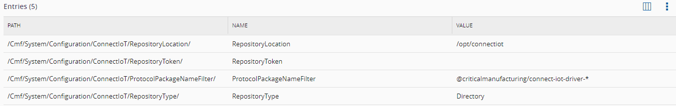
There are several configuration entries that need to be set for this scenario. All the Configurations for IoT can be found in the Administration menu and by navigating to the `/Cmf/System/Configuration/ConnectIoT` configuration section.
| Configuration | Description |
| --------------------------- | ---------------------------------------------------------------------------------- |
| `RepositoryType` | Directory (folder location) or NPM repository |
| `RepositoryLocation` | Repository Location |
| `ProtocolPackageNameFilter` | A name filter to select which packages exist in the repository regarding protocols |
| `RepositoryToken` | Used for NPM authentication |
Table: Connect IoT configuration entries
These configurations will impact the available packages and versions when creating the **Automation Protocol**, **Automation Driver Definition** and **Automation Manager** later on. Here is an example of these configurations:
### Enable Connect IoT for Entity
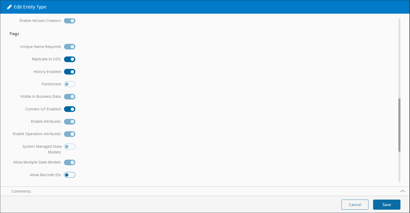
One of the great advantages of coupling the Connect IoT configuration with the MES, is the process context the MES provides. In order to create that link, the MES needs to know what entities are going to be used for Connect IoT. Some of the most common examples a Resource, Area or Site, but of course you can link to whichever entity that makes sense for your use case.
In this case, we will choose a **Resource**, so that we can mimic the operation of an equipment on the shop floor.
Go to `Administration > Entity Type`, select the **Resource**, select `Edit` and set the **Connect IoT Enabled** option to `true`.
### Connect IoT User
Simultaneously, the MES user must be specifically set as enabled to use Connect IoT. This setting can be changed by going to `Administration > Security > Users`, selecting the user that should have permissions to run Connect IoT, selecting `Edit`, and setting the value for the **Integration User** option to `true`.
## Create Automation Protocol
The first step of our integration will be to create the Connect IoT configuration entities.
Go to `Business Data > Automation Protocol`, select `New`.
1. Select the **Create** button to create a new **Change Set** or select an existing one. If you are creating a new one, enter the name, type, and select the **Create** button.
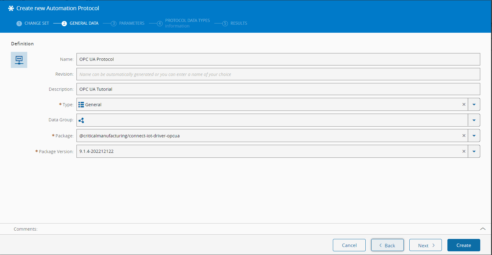
2. In the General Data step, provide:
- A name that represents the Automation Protocol - `OPC UA`
- A description
- The type (for classification purposes)
- `@criticalmanufacturing/connect-iot-driver-opcua` as the package name.
- The dropdown list uses the package repository and only shows the protocol packages that are filtered by the value set in the `/Cmf/System/Configuration/ConnectIoT/ProtocolPackageNameFilter` configuration
- In this dropdown you will see all packages that are available for use
- The package version
- Select **Next**
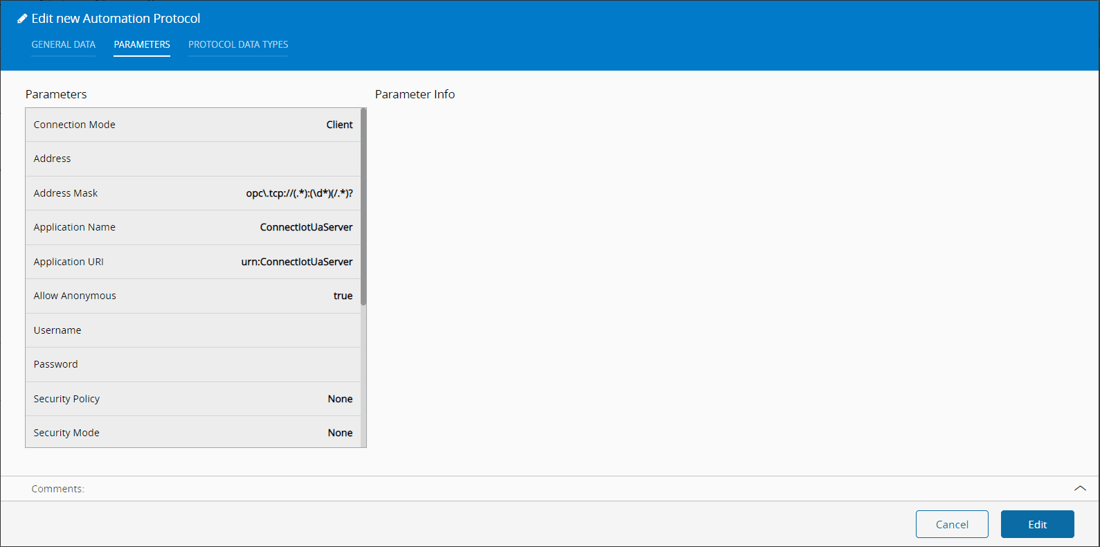
3. Set the default values for the OPC UA protocol parameters
- These values can be individually overridden by the **Automation Controller** workflows. In this step we will only define what are the default values for all automation controller workflow logic that will use this protocol.
- Note that the parameters and some default values are automatically set. This values can be overriden at any point while creating the **Automation Protocol**.
- Select **Next**.
- Select **Create**
!!! info
The next steps, while not interactive, provide information regarding the protocol.
We now have an entity in MES that represents the OPC UA communication protocol and that will be requested by the Automation Monitor when used on a Connect IoT deployment. The package and respective version will be requested from the repository by the monitor, which will then requests the manager to execute the package.
## Create Automation Driver Definition
Go to `Business Data > Automation Driver Definition`, select `New`.
1. Select or create an existing **ChangeSet**. Select `Next`.
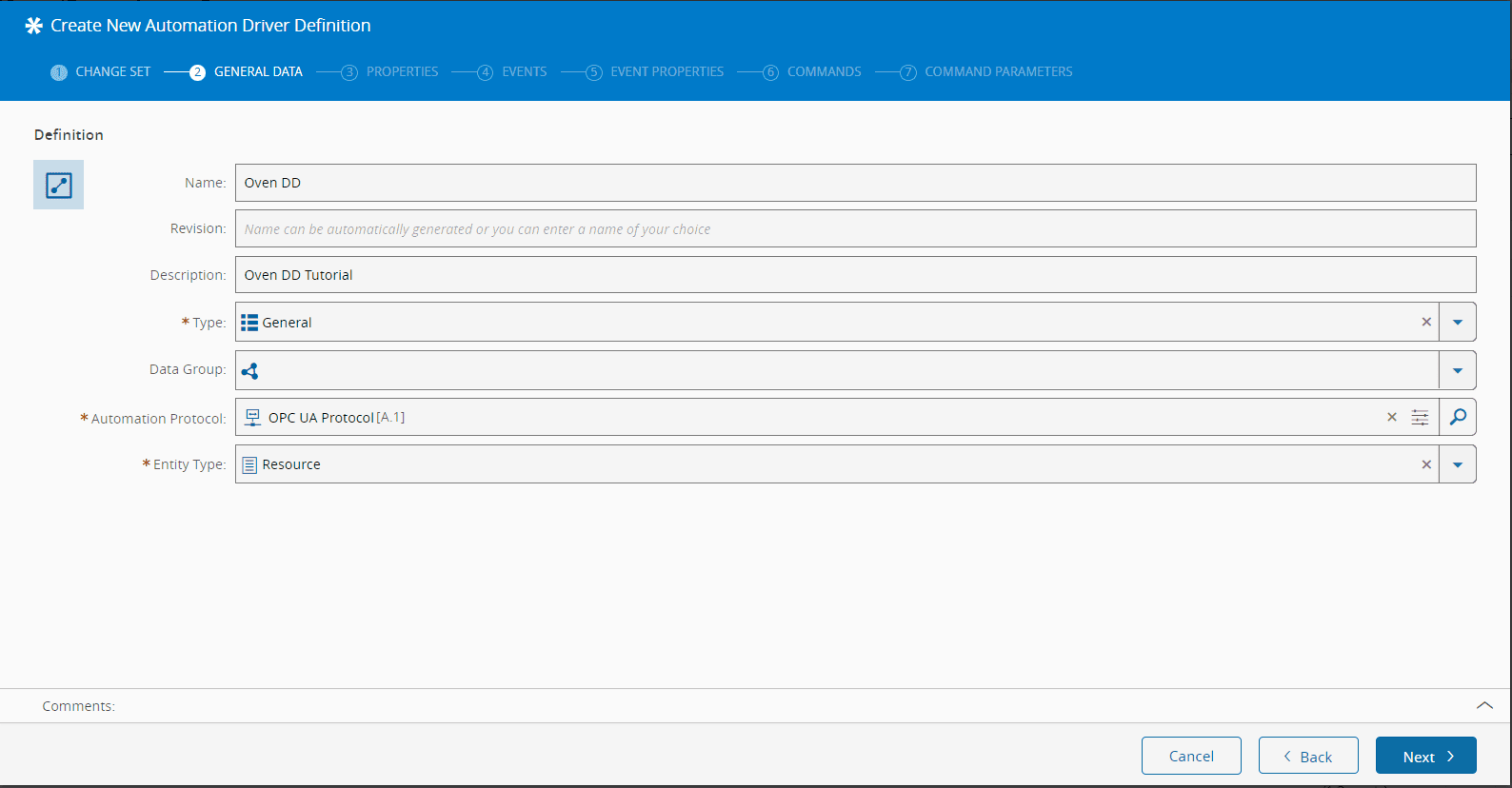
2. In the General Data step, provide:
- A name that represents the **Automation Driver Definition**
- A description
- The type (for classification and reporting purposes)
- The name of the previously created **Automation Protocol**
- The `Resource` as the entity type for the new **Automation Driver Definition**
- This list shows all entities that that are configured with the Connect IoT enabled flag set to `true`.
3. Select `Next` until the Driver Definition is created, since we will not create any additional properties, events or commands.
Notice, that we are not configuring any properties, events or commands. For now this is ok, we are just getting acquainted with the GUI and our goal will be just to connect to the OPC-UA Server.
## Create Automation Controller
Go to `Business Data > Automation Controller`, select `New`.
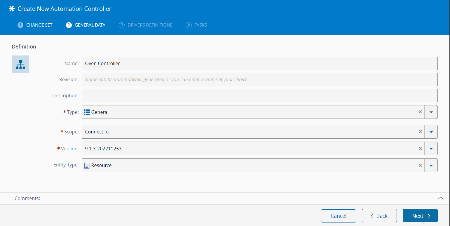
1. In the General Data step, provide:
- A name
- A description
- The type (for classification purposes)
- The scope of this controller (which in this case should be Connect IoT)
- Controller package version
- This is the version of the controller that will be executed.
- The versions used in the **Automation Controller** and on the **Automation Protocol** must be compatible.
- The `Resource` as the entity type for the new **Automation Controller**.
- Select `Next`.
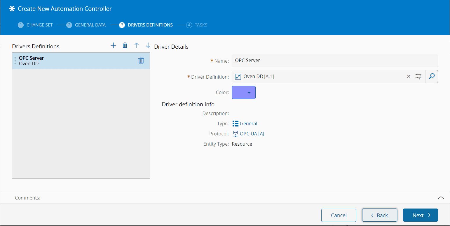
1. In the Drivers Definition step, add a new driver definition by selecting :material-plus: and providing:
- A friendly name.
- The previously created **Automation Driver Definition**.
- A color to identify the tasks that will be associated to a specific driver definition.
!!! note
The color code helps you to identify the tasks related to each driver/machine/resource, so it is a good practice to assign a different color to every driver.
- Select `Next`.
1. In the Task step, select the task packages relevant for the integration itself and available in the workflow designer. For this tutorial, Core Tasks is enough.
- Core tasks: default selection, can't be unselected.
- Critical Manufacturing and Factory Automation tasks are available to every type of workflows.
- All protocols from the drivers under this controller are available to be selected in this task package list (these tasks are listed on the protocol `package.json` file).
- Select `Create`
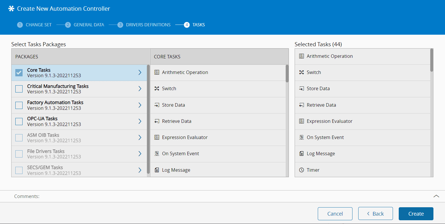
!!! note
Since it is easier to activate packages than to deactivate them due to possible usage in multiple workflow pages, it is advisable to use as many packages as possible for a smoother workflow development. Also, if we had customization, the tasks regarding that customization would appear in this list.
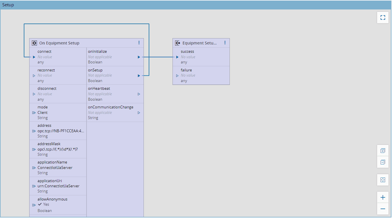
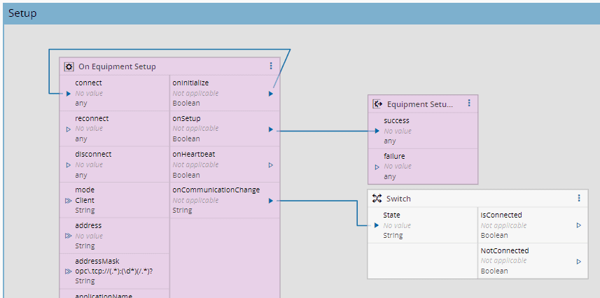
As seen above, a workflow page is automatically created, called `Setup`, containing two tasks:
- `On Equipment Setup`
- `Equipment Setup Result`
Note that they are assuming the color set for the driver definition in this controller. As the workflow logic can get increasingly complex, with a vast number of tasks and links between them, it can become difficult to find the task you are looking for. You can change the line style to make it easier to do this and you can see how to do it in the [[user-guide-workflow-designer]] page.
These are driver related tasks regarding communication configuration and initialization. Let's link them as shown below:
- Link the `onInitialize` output directly to the `connect` input;
- Link the `onSetup` output to the `success` input.
When the connection between the controller and the driver processes is established, the `onInitialize` event is triggered. By linking it to the `connect` input, it indicates the driver process to start configuration and connection to the equipment.
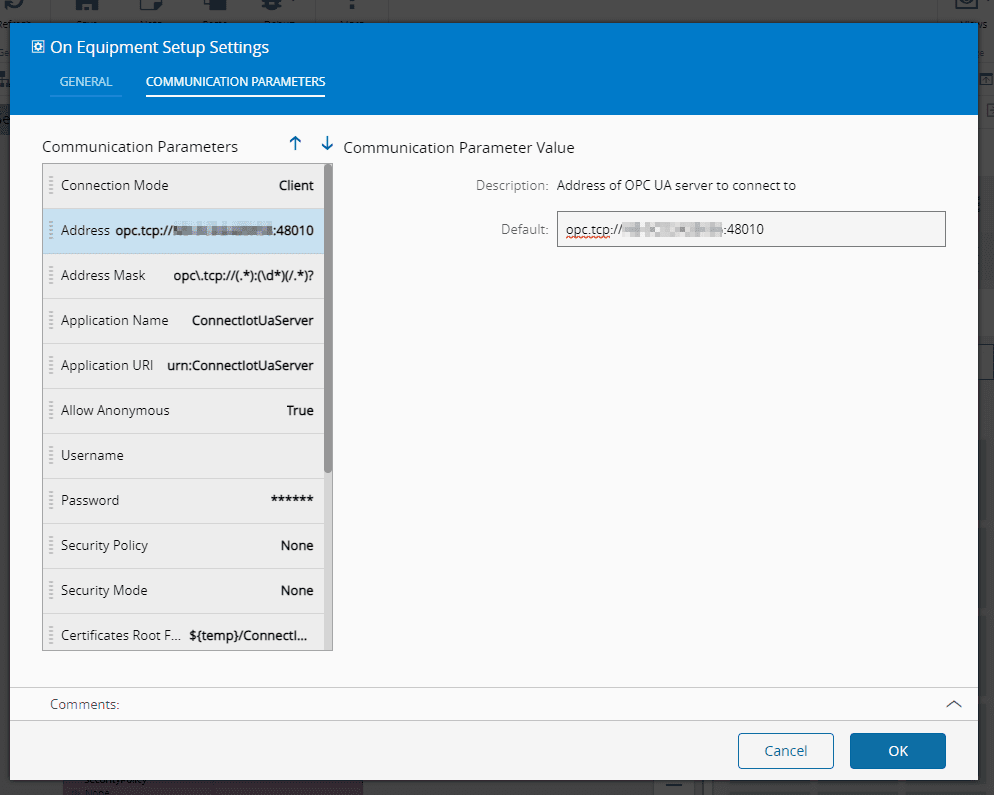
In the `On Equipment Setup` task:
- Select the three dots and select `Settings`.
- Select the Communication Parameters step
- Set the device address on the Address Parameter - i.e `opc.tcp://localhost:48011` - The address will be provided by the `UaCPPServer` described in the **Equipment Simulator Tests** section, feel free to leave it empty and fill it later.
- Select `OK`
All information regarding `On Equipment Setup` Task can be found here: [[user-guide-automation-task-core-equipmentsetup]]
### Communication Workflow
The communication between the controller and the driver processes follows a state model, creating a workflow of communication. The goal is to ensure stable communication when the process reaches communicating state. If it doesn't achieve stable communication, the process enters into a retry loop until it connects successfully.
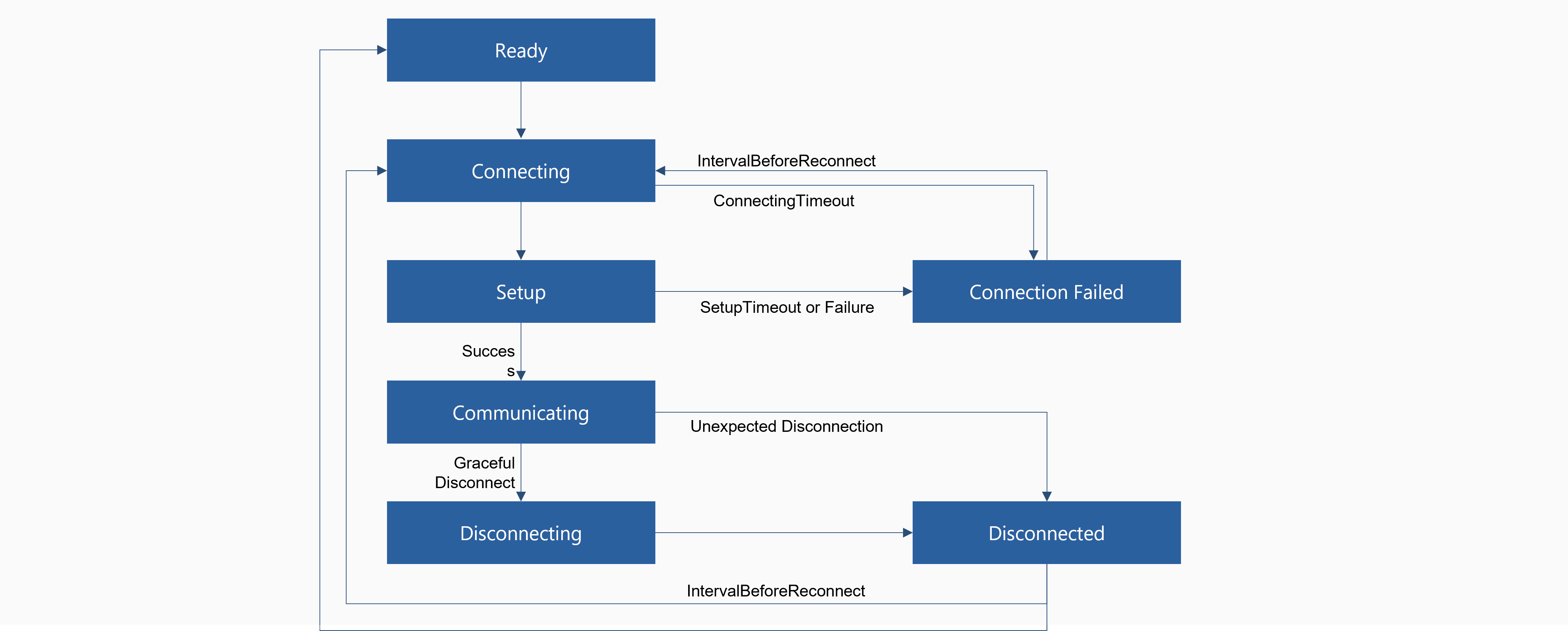
| State | Description |
| --------------------- | ---------------------------------------------------------------------------------------------------------------------------------------------------------------------------------------------------------- |
| **Ready** | Connection is ready to be established |
| **Connecting** | Action was received to start the connection, when `Connect` is activated, and starts to stablish the connection |
| **Setup** | When the connection to the device is successful, and the `onSetup` output is sent (if this property is not changed then it goes to the next state (**Connecting Failed**)) |
| **Connecting Failed** | When the connection failed after the defined time out, transitioning from **Connecting** to **Connecting Failed**
When `setupTimeout` or setup failure, transitioning from Setup to Connecting Failure |
| **Communicating** | When the `onSetup` event outputs a successful connection, the device is now with a stable communication |
| **Disconnecting** | When the automation is disconnected with a graceful disconnect |
| **Disconnected** | The result of disconnecting process or of an unexpected disconnection |
Table: Communication States
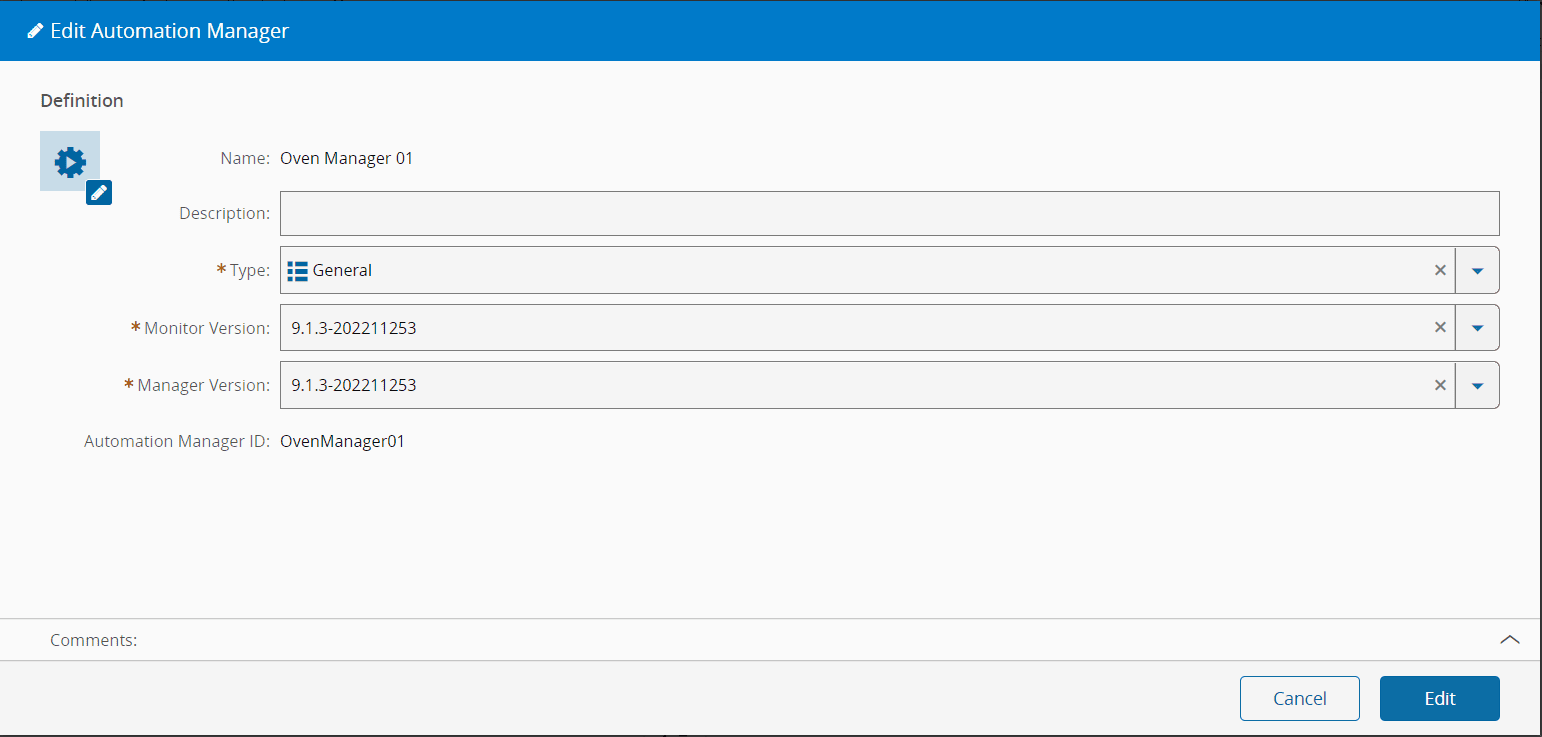
## Create Automation Manager
Go to `Business Data > Automation Manager`, select `New`.
In the General Data step, provide:
- A name
- A description
- The type (for classification or reporting purposes)
- A unique name as the **Automation Manager** ID, which will be referred to when performing the installation
!!! warning
Do not use spaces in the name to facilitate the command line usage
- Select `Create`
## Runtime
As a summary, this is what was configured:
- An **Automation Protocol**: OPC UA
- An **Automation Driver Definition**: Oven DD
- An **Automation Controller**: Oven Controller, liked to the driver definition, and with the address of the protocol server
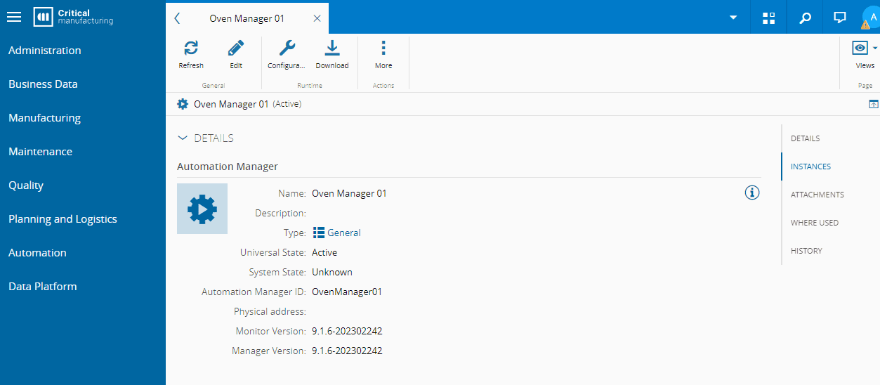
- An **Automation Manager**: Oven Manager 01.
Now we need to export the configuration to a runtime scenario.
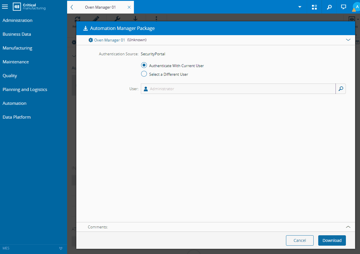
1. Start with downloading the Automation Manager by going to the Automation Manager and selecting `Download` from the top ribbon.
!!! info
The users that are available for selection are the ones that have the property `Integration User` set to `true`.
2. After downloading the file (in `.zip` format), extract the files within the zip folder.
!!! note
While development is ongoing, it is recommended that the Automation Manager runs in console mode, so you can have immediate information on the status of the manager without the need of going through service logs, as well as to enable quick start and stop control over the application. When the development has ended, and ready to be in production, the Automation Manager can be executed as service.
!!! note
Running the Automation Manager as a service and using the console mode simultaneously might not work for some protocols.
3. To start the Automation Manager, go to the Scripts folder of the extracted files and run `startConsole.bat`.
4. Now you have a running Automation Manager that does not contain any controller or driver yet. To do this, we need to create an instance in the Manager on the MES GUI.
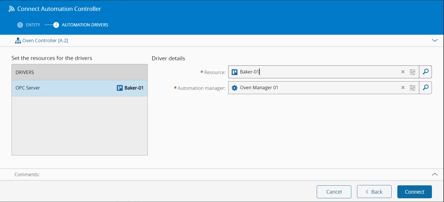
- Go to `Business Data > Automation Controller`, select the created **Automation Controller**, open the Details view and select `Connect`.
- You must provide an appropriate **Resource** and the Automation Manager this instance will be associated to. Choose the **Resource** and select the **Automation Manager** created above.
- Select `Next`.
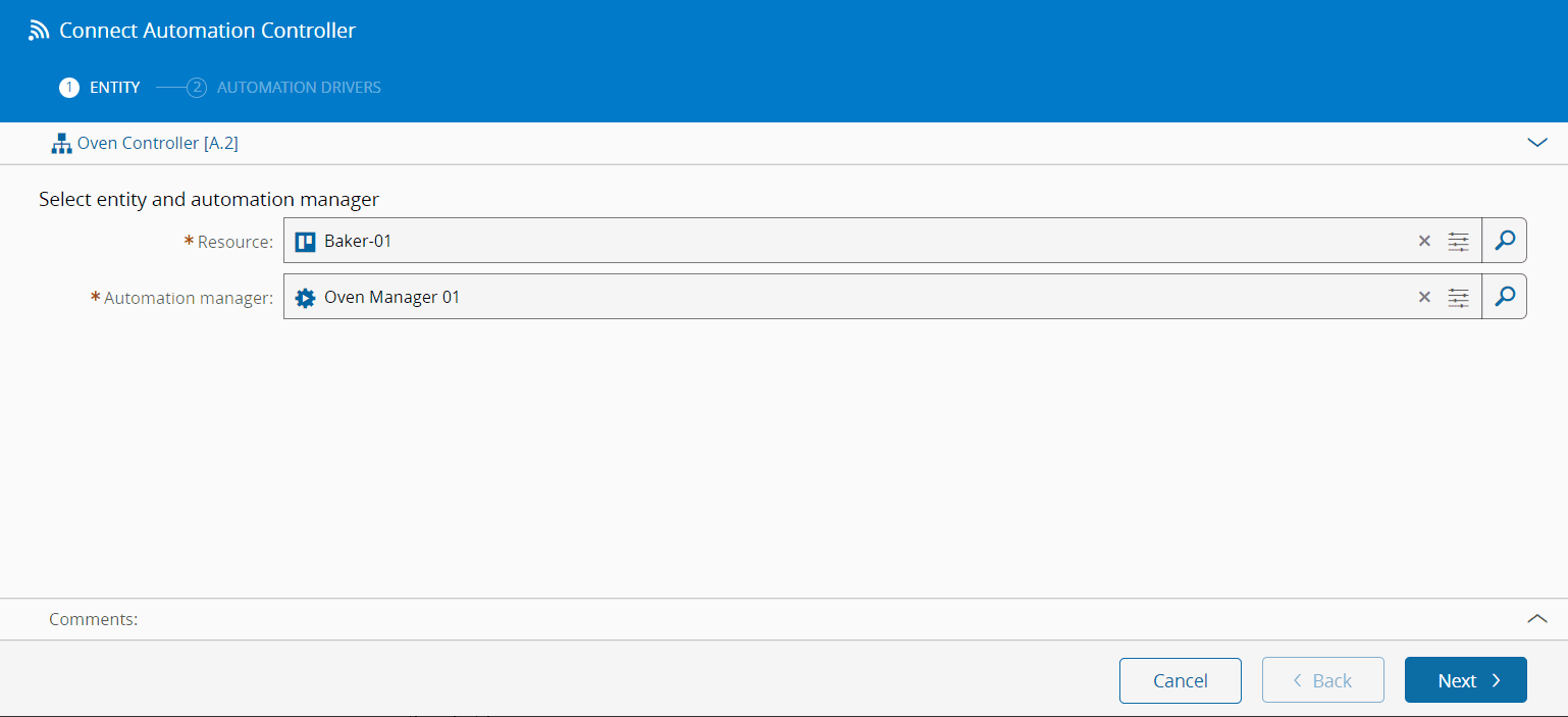
- In the Automation Drivers step select the **Automation Driver Definition** and choose the same **Resource** chosen before.
You now have a structure to build the Connect IoT business logic, and its device connection.
Now let's try to run the program. For this scenario, in order to decrease complexity, we are not deploying the Automation Manager through the DevOpsCenter in a containerized installation, but running it as an executable. In the Automation Manager download the zip package.
It will now download a zip file, you can extract it. Here we will have everything we need to run the application.
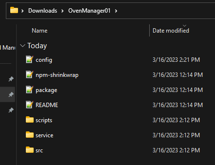
The config file is key to all the configuration, feel free to take a look at what is there and all the variations, you can also look at [[installation-guide-connectiotautomationmanagerconfig]] for more details. The configuration in the Automation Manager will be the one used by the running process and can be updated. Nevertheless it will only be changed after a restart of the application.
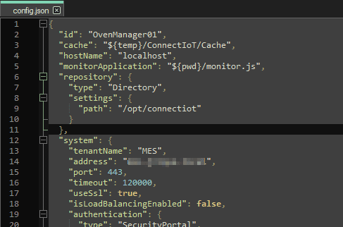
!!! note
If you are using an MES installation in containers, the path that is in the config RepositoryLocation is not the same as the one in the config of the Connect IoT application. The path in the MES will be the perspective from the MES, whereas the one you download is from the perspective of your local application.
For example, in this MES installation the path is /opt/connectiot, which is the container mount. In your config under repository change the path to what is applicable in your use case, the one used in this tutorial was `\\wsl.localhost/Ubuntu/mes/iot-repository`. In order to diagnose this problem look out for the error `error: Failed to resolve package`.
Let's start by running the StartConsole in the `scripts` folder.
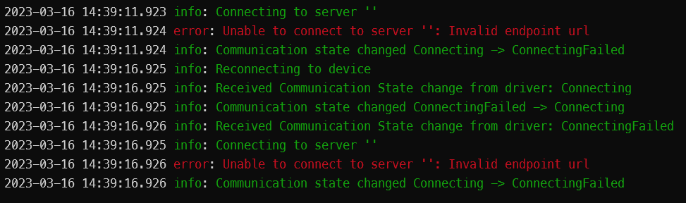
The output of the console is very helpful and informs us to what the process is doing and also to troubleshoot. Looking at the error message we can see that we have a connection loop, because it is failing with `error: Unable to connect to server : Invalid endpoint url`. Remember we are trying to connect to an OPC-UA server, so we need to specify the OPC Server address. For this tutorial we are going to have the address hardcoded in the Automation Controller, but in normal scenarios you want to be more dynamic.

In the settings of the `On Equipment Setup` task, provide an address to your OPC-UA Server. If you don't have an OPC-UA server refer to the next chapter on Equipment Simulator Tests.
Select ok and save your changes in the Automation Controller. Going back to the application you can see that after saving in the MES it automatically sent the change to your Automation Manager running as is know able to connect.
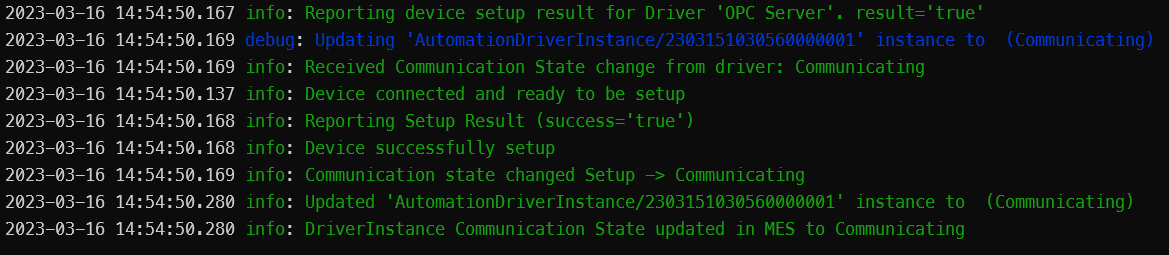
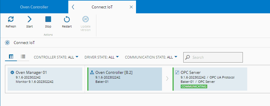
The MES GUI can also provide feedback of the status of the communication. Selecting `Automation > ConnectIoT`, you have a global vision of all the communications.
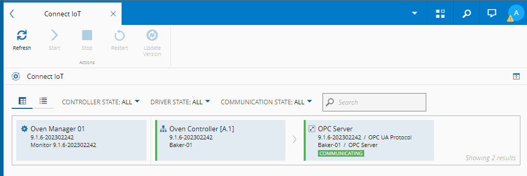
We are connected to the machine, in this case an OPC Server.
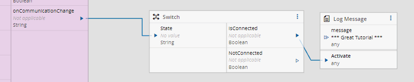
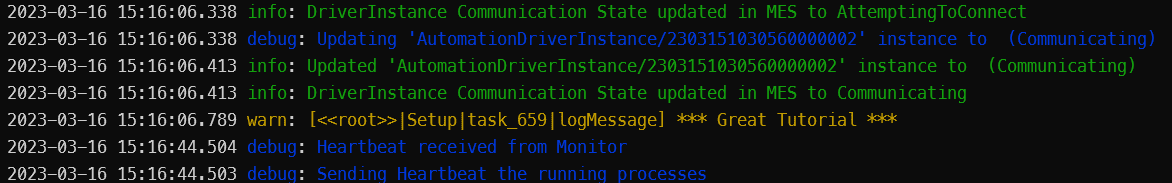
Let's finish this basic training by, logging a message saying "*** Great Tutorial \*\*\*" when the machine is on the state communicating.
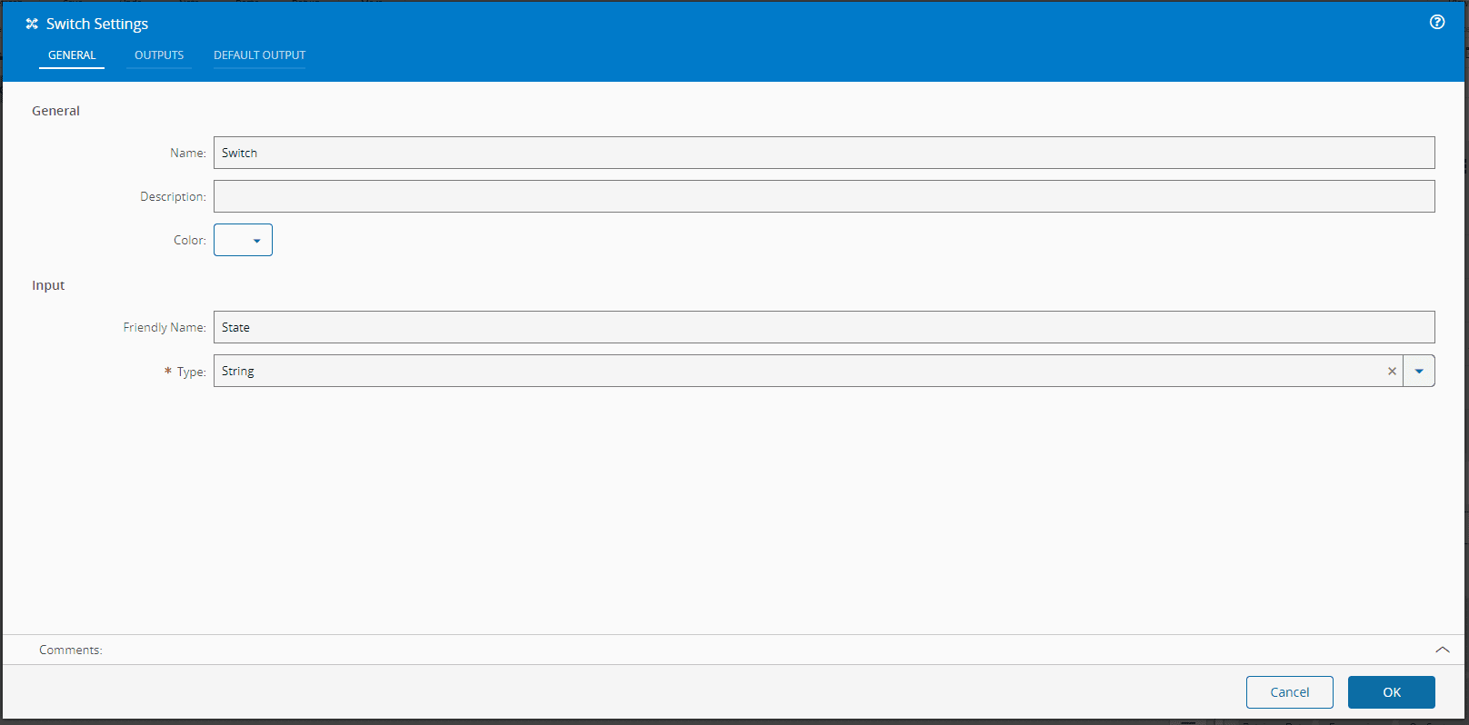
Go back to the Automation Controller Workflow and add a task `Switch`.
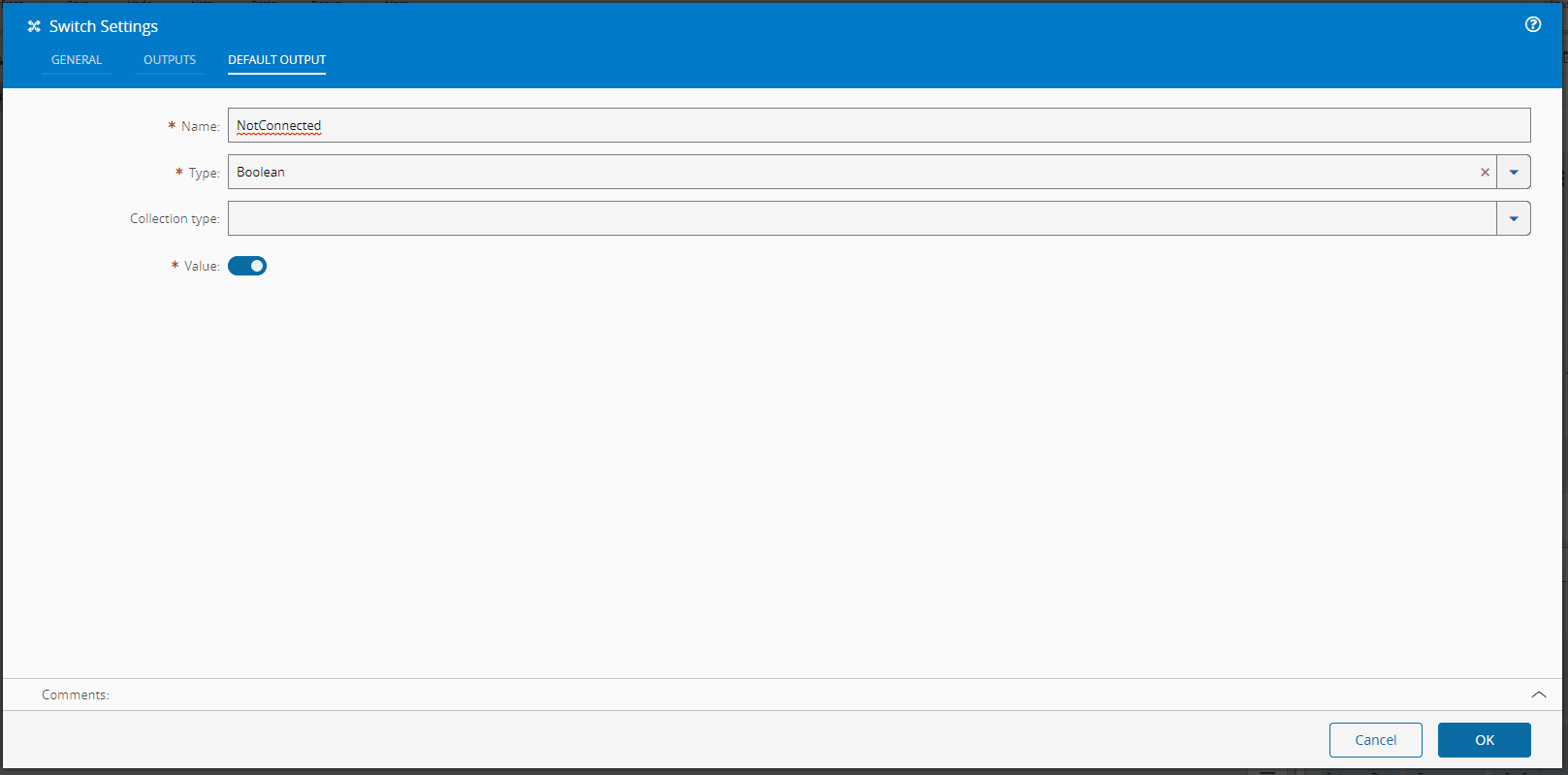
In the `Default Output` we will add a Name - `NotConnected` with type `String`. If the input `State` has no match, the default output will emit.
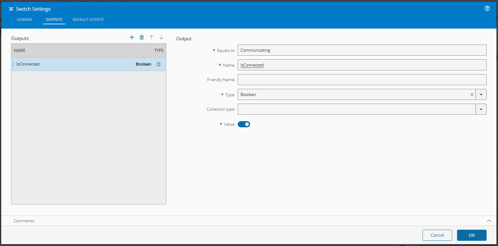
In the outputs, we add an `IsConnected` output, and in this output we will say, that if the State is equal to `Communicating`, it will emit `true`.
Now we can link it to the `onCommunicationChange` of the `OnEquipmentSetup`.
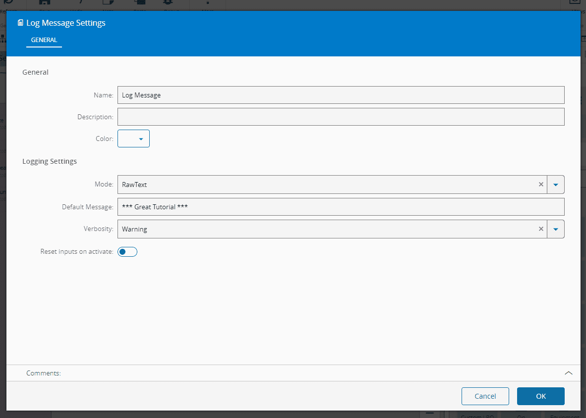
We will now add our log message. To do so, drag and drop a `Log Message` task. Here, we will add the message as our Default Message and change the verbosity to Warning so it's easier to spot in the console output.
Lets now finish the flow by connecting it to the `Switch` task.
In the `Automation > ConnectIoT` tab, in the MES system restart the controller. In this case we are restarting the application as we want to force it to connect again.
Going back to the console we can see the message now appearing after connecting.
You now have a built structure using Connect IoT that can connect to an equipment, and this is the end of the basic configuration tutorial. The intermediate scenario configuration will be built upon this.
## Equipment Simulator Tests
In order to test this integration tutorial, we can use a free OPC/UA server (to mimic the behavior of an equipment) available at as well as an OPC/UA client (to set the values of the server accordingly), available at .
1. Go to the websites listed above to download and install the UaCPPServer server software and Unified Automation UaExpert client software.
2. Start the server.
3. Run the UaExpert client. Add a server, set the Endpoint Url to the server displayed on UaCPPServer, and select `OK`
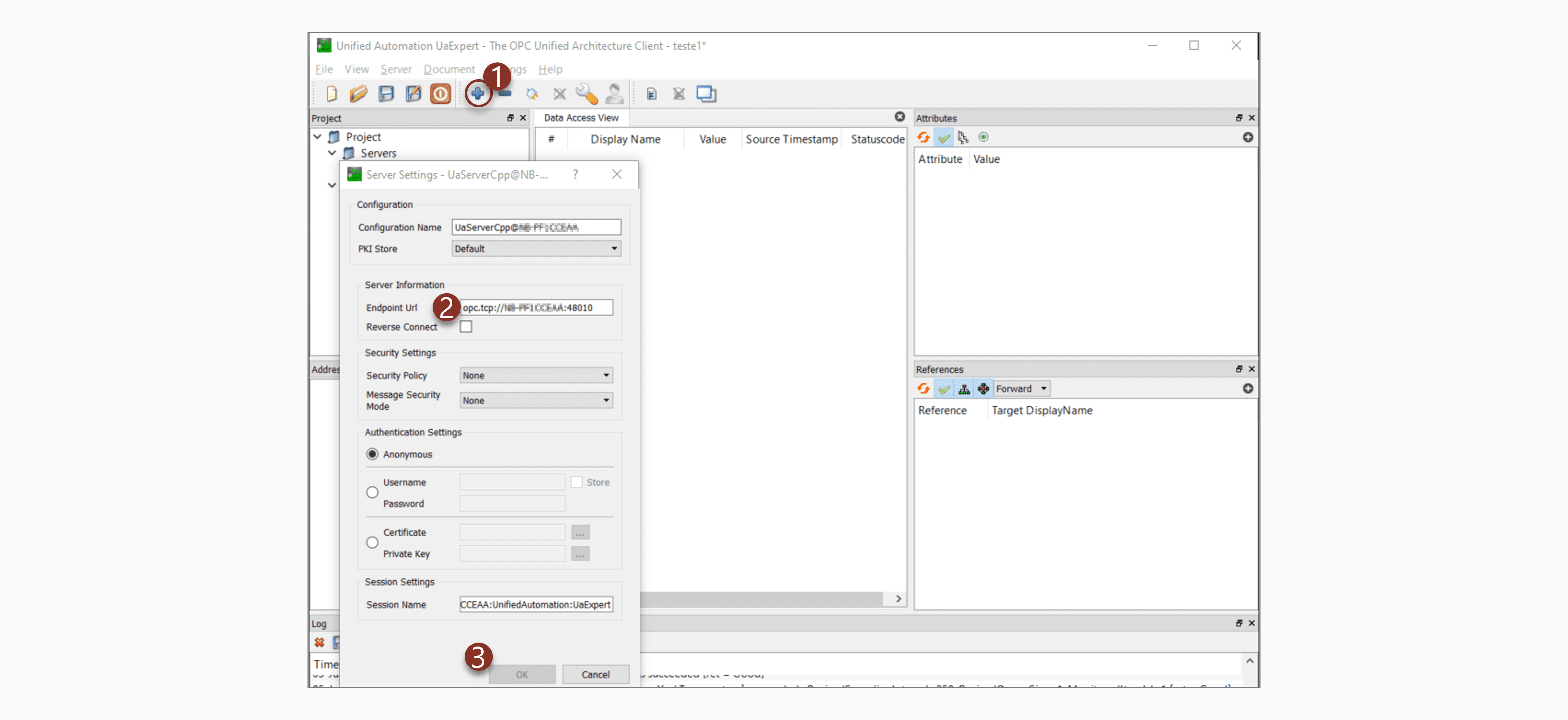
The values given here are examples, replace it with yours.